Uploads by Brendlefly62
From Gentoo Wiki
This special page shows all uploaded files.
| Date | Name | Thumbnail | Size | Description | Versions |
|---|---|---|---|---|---|
| 12:43, 11 March 2025 | X4 w rp2040 sontrolling status LEDs 20250311 083006.jpg (file) |  |
633 KB | Radxz X4 with RP2040 controlling status LEDs | 1 |
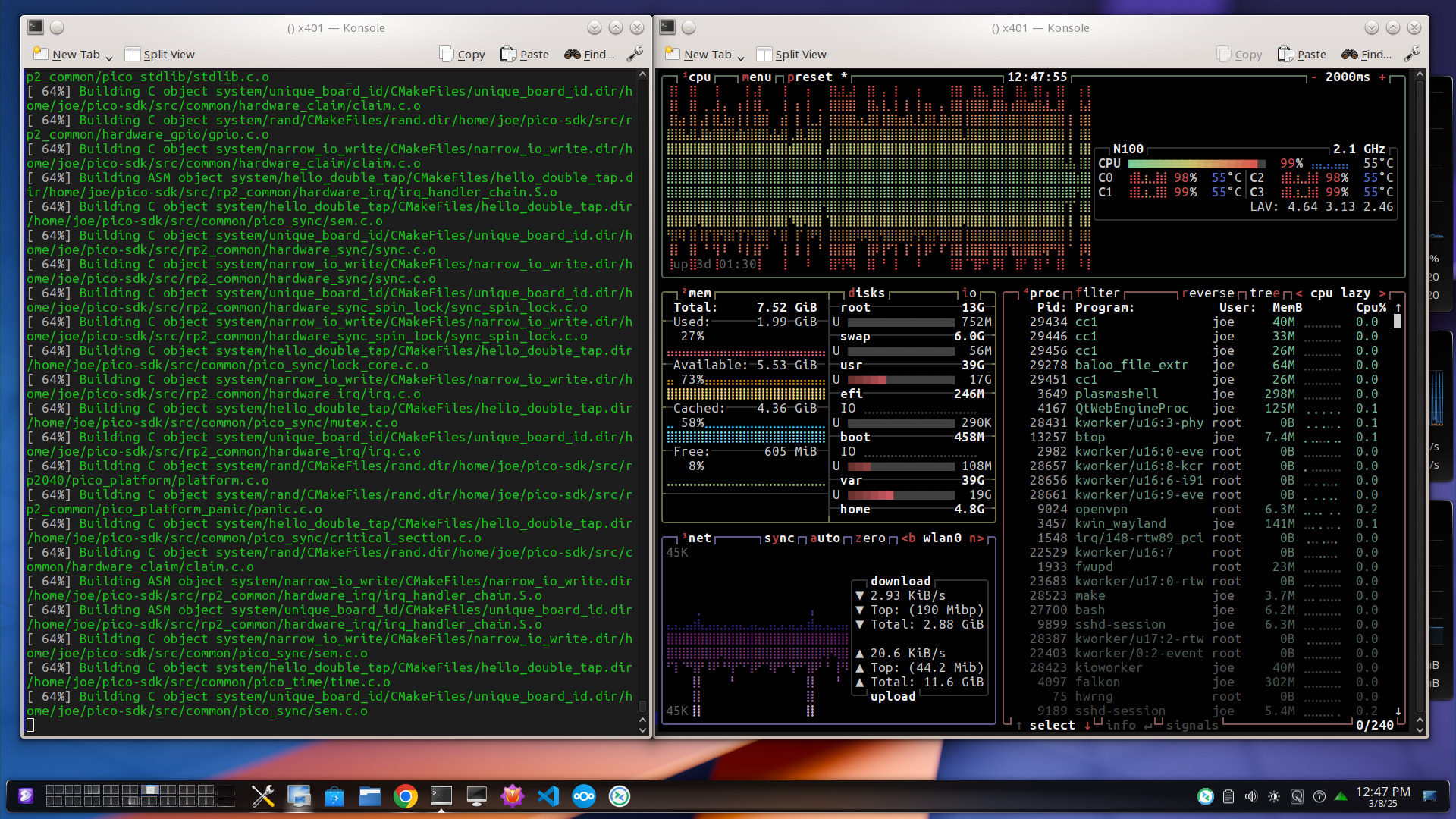
| 22:00, 8 March 2025 | X4 compiles gcc for rp2040 w btop-3.png (file) |  |
574 KB | X4 compiles gcc as part of cross-toolchain for its rp2040 microcontroller | 1 |
| 21:58, 8 March 2025 | X4 compiles pico-examples for rp2040 w btop.png (file) |  |
748 KB | X4 compiles pico-examples for its rp2040 microcontroller | 1 |
| 21:26, 8 March 2025 | X4 RP2040 w LEDs 20250308 133509.jpg (file) |  |
357 KB | RP2040 on Radxa X4, controlling LEDs on GPIO pin header | 1 |
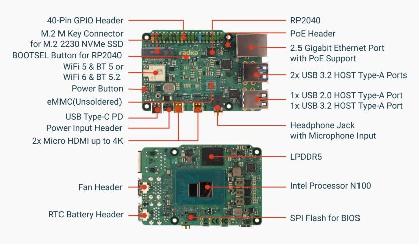
| 16:31, 5 March 2025 | Radxa X4 Layout.png (file) |  |
305 KB | Radxa X4 board layout | 1 |
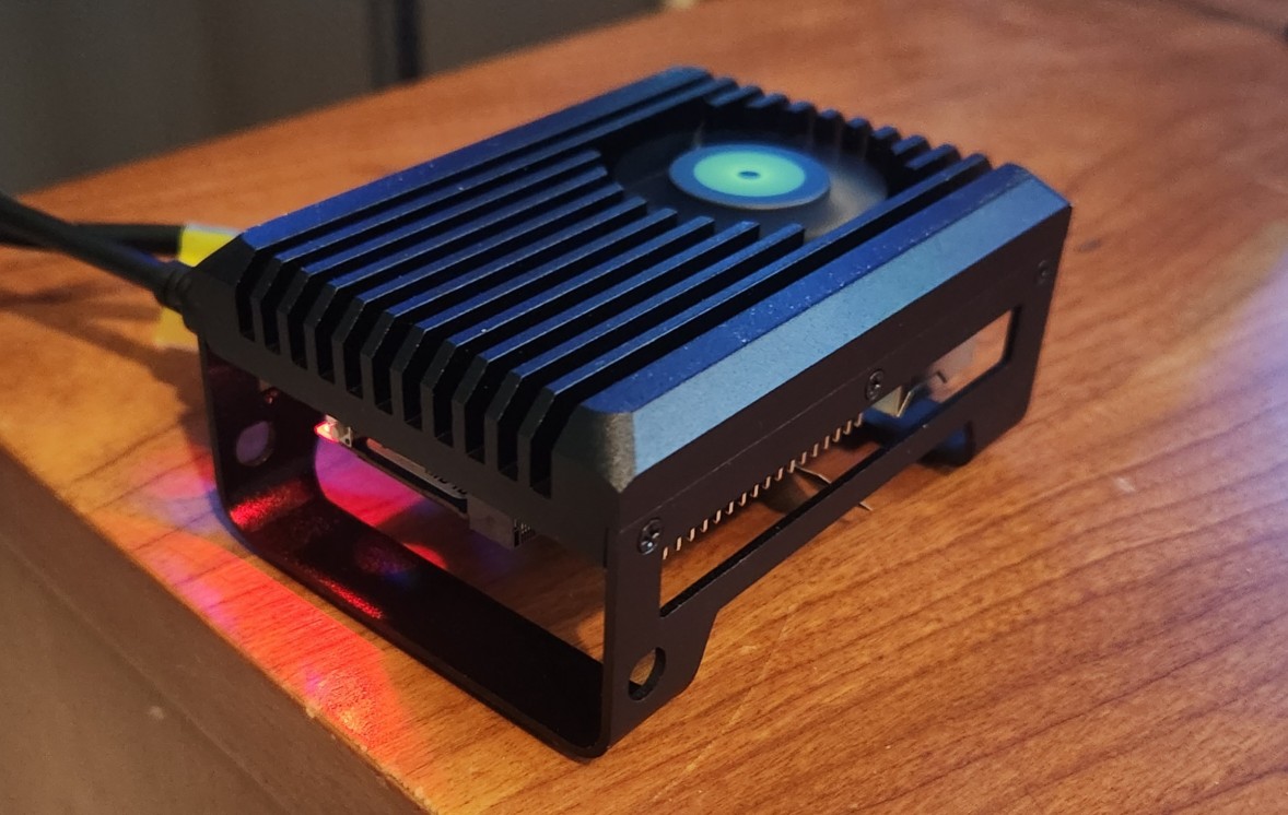
| 16:26, 5 March 2025 | X4 cooler 20250305.jpg (file) |  |
169 KB | Radxa X4 cooler (sbc mounted under) | 1 |
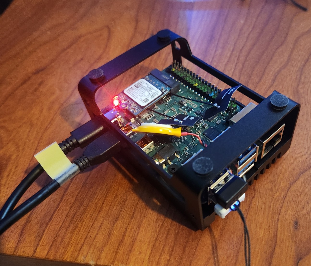
| 15:13, 5 March 2025 | X4 mounted 20250305.jpg (file) |  |
330 KB | Radxa X4 sbc, mounted on cooler, with USB-C power, micro HDMI cables connected and USB storage, USB keyboard/mouse dongle inserted. The device is actually shown inverted here, since the cpu is mounted on the bottom of the sbc, and it is affixed to its cooler from "below", for normal operation, the entire unit is turned over, to sit on 4 x rubber feet depicted in this photo. Note also visible in the picture are 128G NVMe M.2 stick, real-time clock battery, and wifi antennae. | 1 |
| 18:00, 10 August 2024 | Rock-5c nvme 20240810 134525.png (file) |  |
1.86 MB | Radxa Rock 5c SBC shown here with Geekworm pcie nvme under-"hat" hosting 1G nvme luks-encrypted rootfs consisting of several lvm lvs unlocked and mounted via custom initramfs, with boot device on microSD card. Also shown: hdmi, 3A usb-C PSU, usb wireless keyboard/mouse dongle, usb storage used as external keying device for luks, ethernet cable, status leds useful in headless operation, and uart-serial console hookup for u-boot monitoring via usb-ftdi-putty connection to nearby PC | 1 |
| 20:29, 29 July 2024 | Rock5c SerialConsole Hookup 2024-07-29 162759.png (file) |  |
489 KB | rock 5c serial console | 1 |
| 01:39, 28 July 2024 | Rock5cPackaging 20240727 160215.png (file) |  |
1.75 MB | rock 5c packaging | 1 |
| 22:21, 27 July 2024 | Rock5c BoardLayout Screenshot 2024-07-27 181940.png (file) |  |
457 KB | rock 5c board layout | 1 |
| 22:18, 27 July 2024 | Rock5c GPIO Screenshot 2024-07-27 181709.png (file) |  |
75 KB | rock 5c gpio layout | 1 |
| 20:14, 27 July 2024 | Rock5c 20240727 160039.png (file) |  |
1.95 MB | Radxa Rock 5c shown here with hdmi and ethernet connected; power is supplied by 5v 3A USB-C; GPIO pins 6 (GND), 8 (TX), 10 (RX) are wired for uart serial console access; and the wifi antenna is visible | 1 |
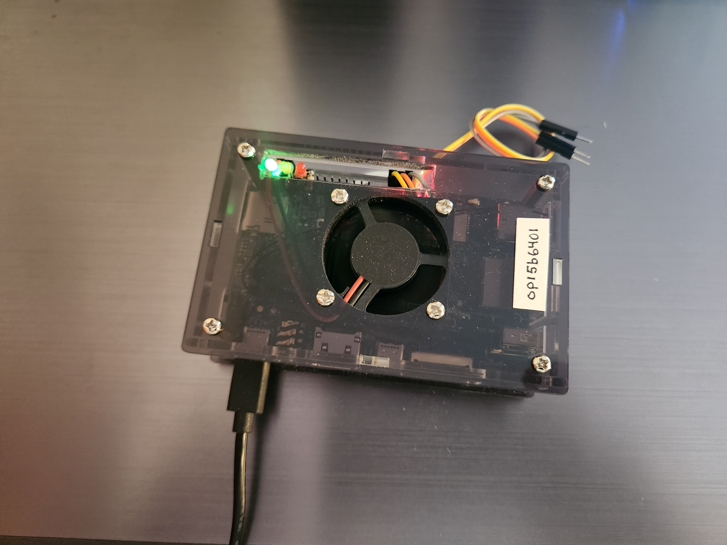
| 22:45, 14 July 2024 | Opi5b uncovered-2 20240714 183757.png (file) |  |
1.93 MB | OrangePi 5b, uncovered. More "vertical" view | 1 |
| 22:44, 14 July 2024 | Opi5b uncovered-1 20240714 183748.png (file) |  |
1.76 MB | OrangePi 5b, uncovered. Note antennae, USB, GigE ports, heat sink... | 1 |
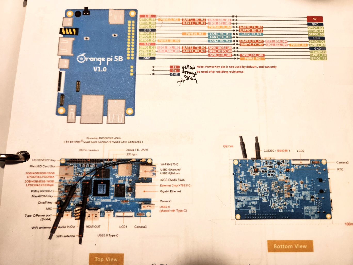
| 19:03, 14 July 2024 | Opi5b layout 20240714 144400.png (file) |  |
1.79 MB | Photo of OrangePi 5b layout. 26 pin expansion header; top/bottom views | 1 |
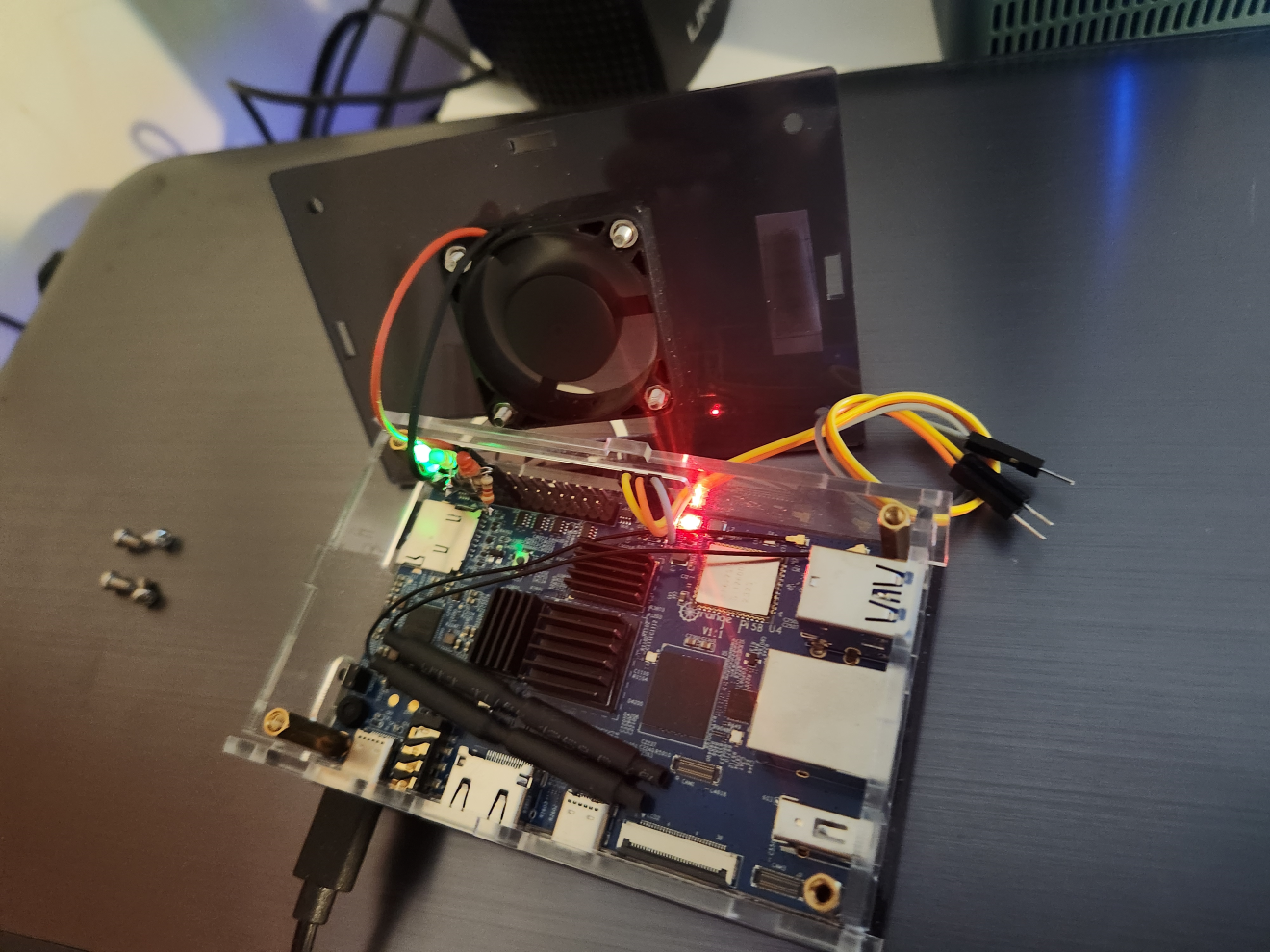
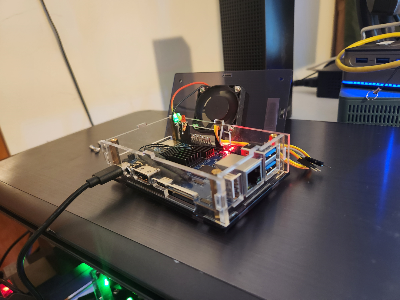
| 17:40, 14 July 2024 | Opi5b 20240714 132742.png (file) |  |
1.85 MB | OrangePi 5b in "GeekPi" case, shown with switched 3A power supply attached, and 3 x LEDs connected for monitoring headless status of VPN, services, and cpu temp; also shown with uart header wired for connection to FTDI-USB serial monitor on PC | 1 |
| 21:35, 13 May 2024 | 20240513 171715.png (file) |  |
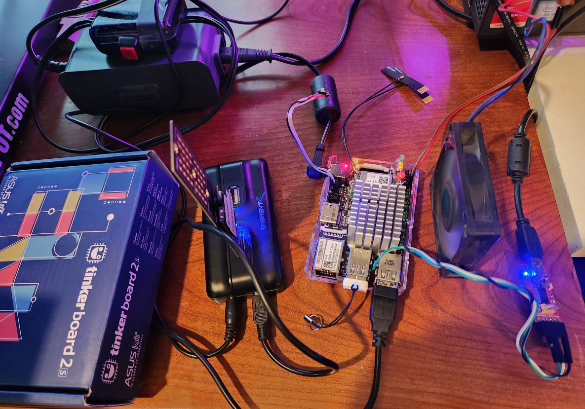
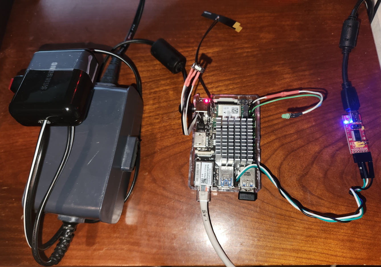
1.89 MB | Tinkerboard 2s, debug UART connected to PC, NVME via USB-hub for encrypted rootfs, keyfile on tinyUSB, heatsink/fan, status LEDs, antenna, connected to network via VPN | 1 |
| 15:11, 8 May 2024 | Tinker2s layout reduced.png (file) |  |
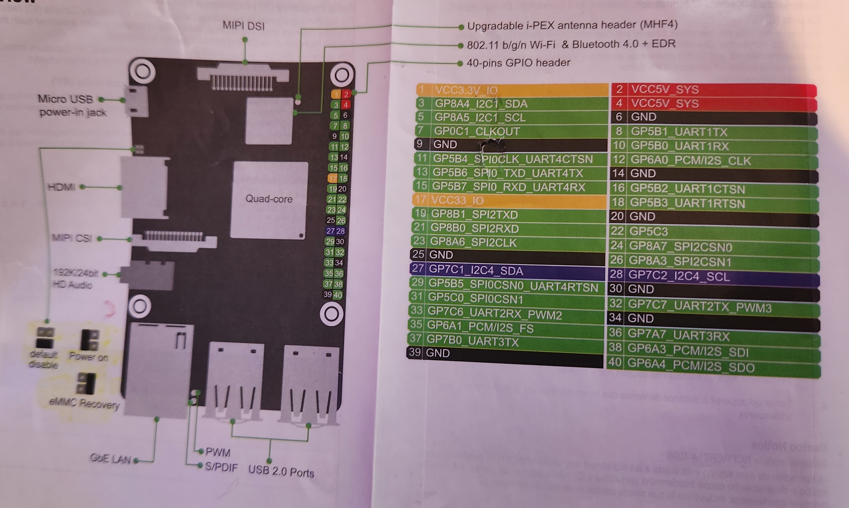
1.8 MB | Photo of layout depicted in quickstart guide distributed by OEM | 1 |
| 13:57, 8 May 2024 | Tinker2s demo reduced.png (file) |  |
1.9 MB | Asus Tinkerboard s, shown here in the bottom half of an old original Raspberry Pi case, for non-conductive protection. The large heatsink shipped was re-used from an old x86 motherboard's coprocessor. This board has an I/O layout similar to RPi 2/3 and might fit those old cases, maybe with some modification to fit the barrel-connector of the 12V power supply. The PSU visible on the left is re-used from an old CPAP machine and was modified to include a switch on its DC supply side. Also visibl... | 1 |
| 23:43, 7 November 2023 | 20231107 183715-2.jpg (file) |  |
266 KB | TinkerBoard S wired for UART/serial console viewing via USB | 1 |
| 23:40, 7 November 2023 | 20231106 130829.jpg (file) |  |
1.39 MB | Annotated layout pages of the user-guide/datasheet that comes with the TinkerBoard S | 1 |
| 16:54, 6 November 2023 | 20231106 113153.jpg (file) |  |
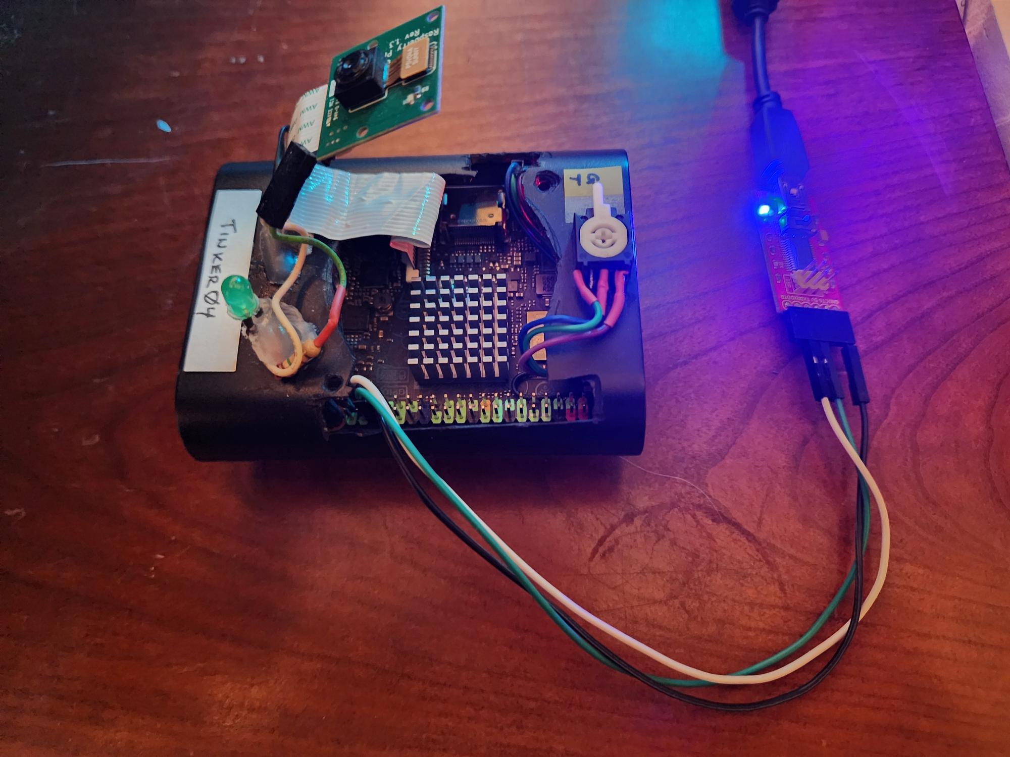
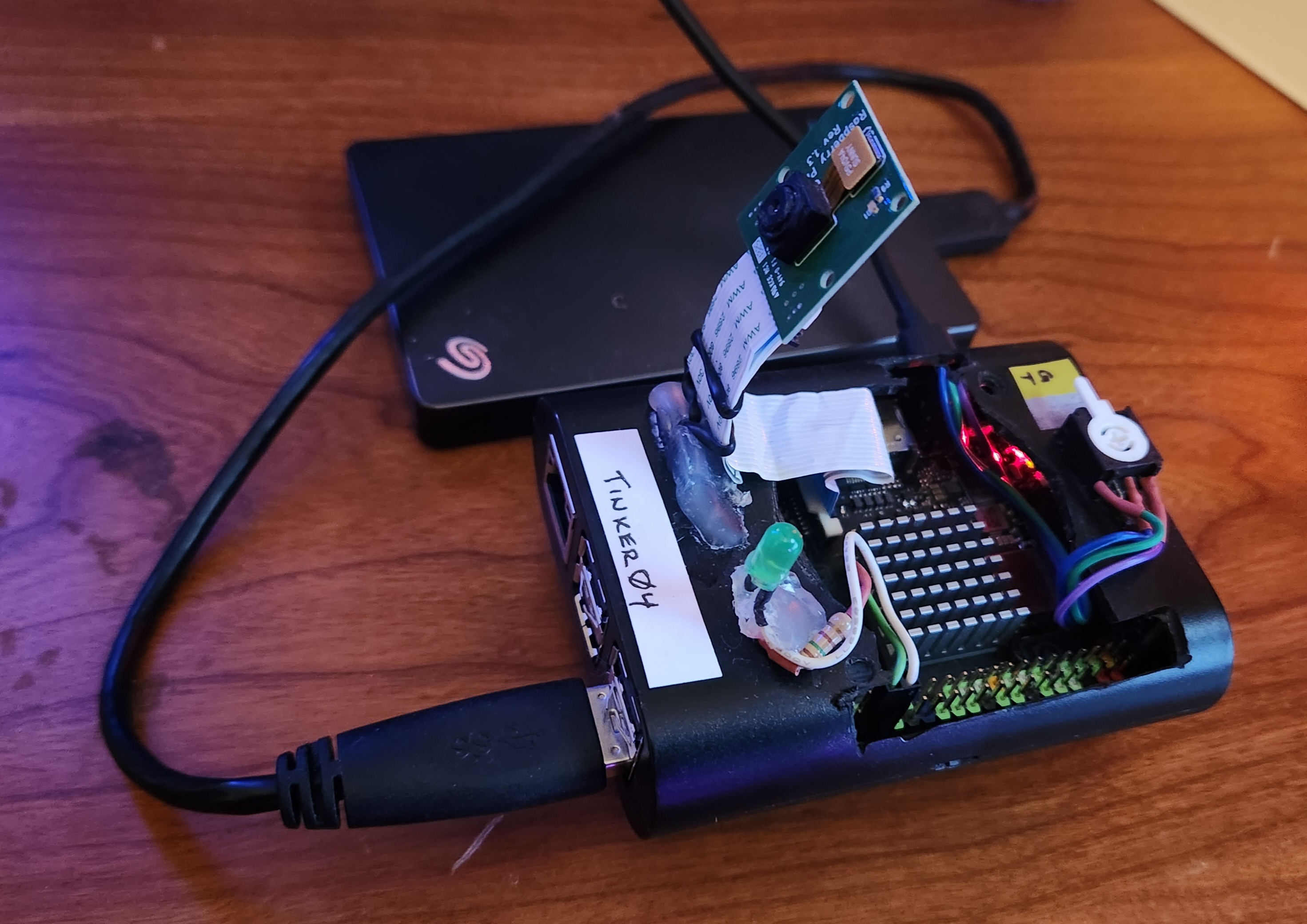
1.19 MB | Asus Tinkerboard s, shown here in an old Raspberry Pi 2 case modified (for ventilation fan used with a Raspberry Pi 3 Model B+ a few years ago). This board has the same I/O layout at RPi 2/3 and is therefor compatible with those old cases. Also visible here is an RPi camera mdule (tested only with Tinkerboard's distributed Android OS), an SPDT switch wired to the Tinkerboard S's "maskrom" jumper - allowing easier selection of either eMMC or SD Card as primary boot device, and an LED used to... | 1 |
| 17:18, 22 October 2023 | DeviceManagerScreenshot 2023-10-22 131042.jpg (file) |  |
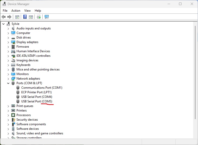
80 KB | Use DeviceManager to confirm serial comm port | 1 |
| 17:17, 22 October 2023 | PuttyScreenshot 2023-10-22 130508.jpg (file) |  |
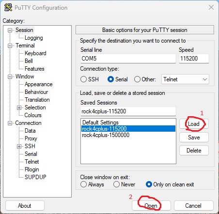
73 KB | Screenshot - using PuTTy for serial console | 1 |
| 02:26, 28 September 2023 | 20230927 215352.jpg (file) |  |
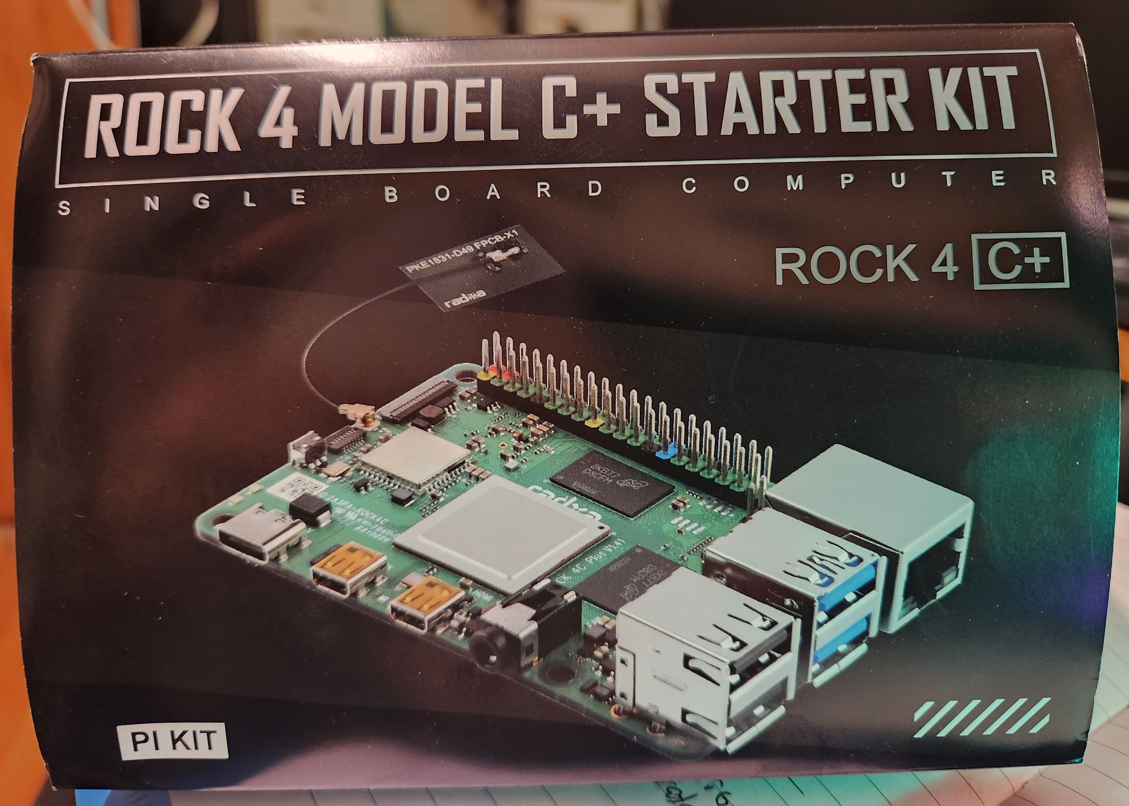
1.56 MB | Rock 4c+. Front of outer packaging with 3D view of board. Photo by user | 1 |
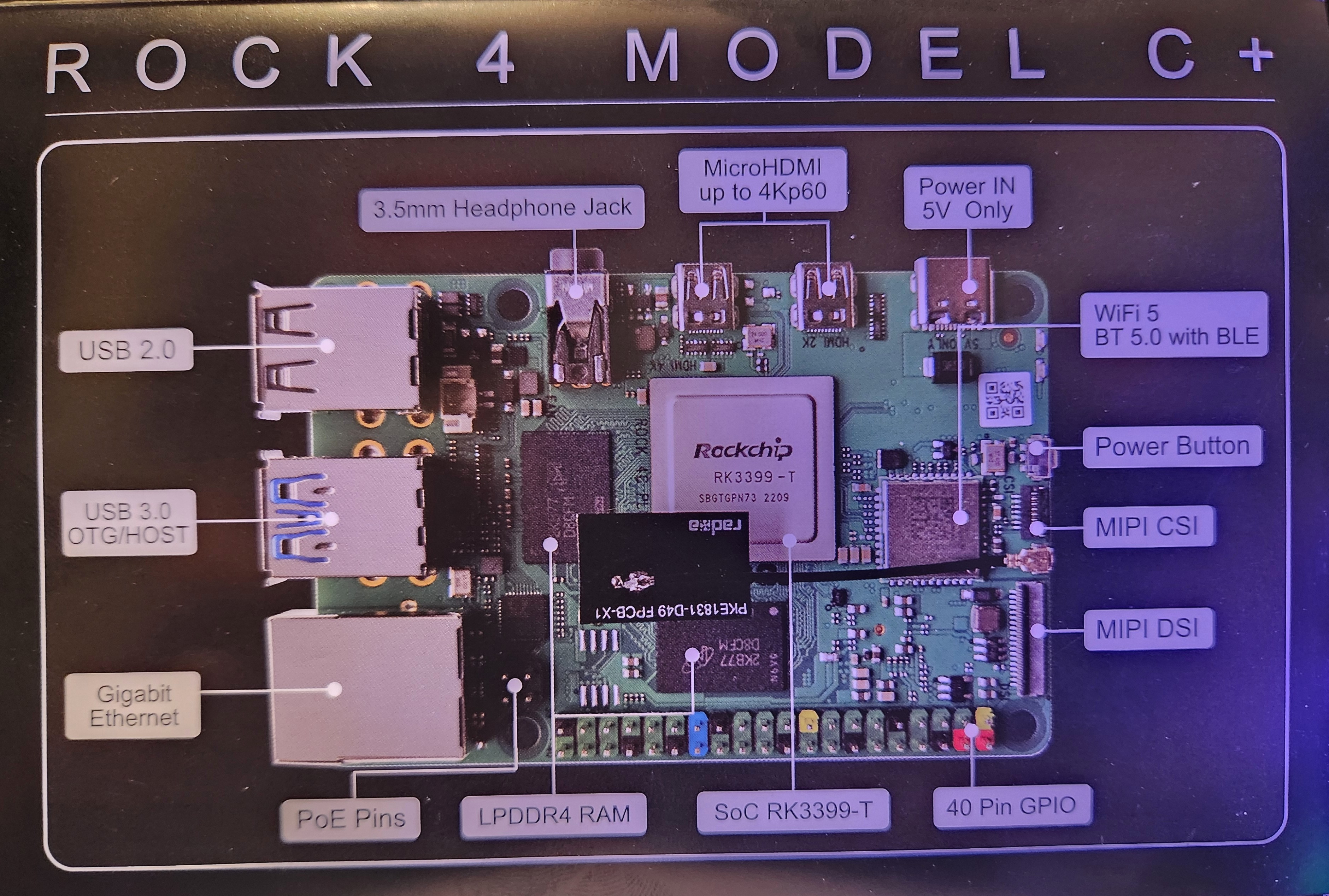
| 02:25, 28 September 2023 | 20230927 215324.jpg (file) |  |
1.79 MB | Rock 4c+. Outer packaging with annotated board diagram. Photo by user | 1 |
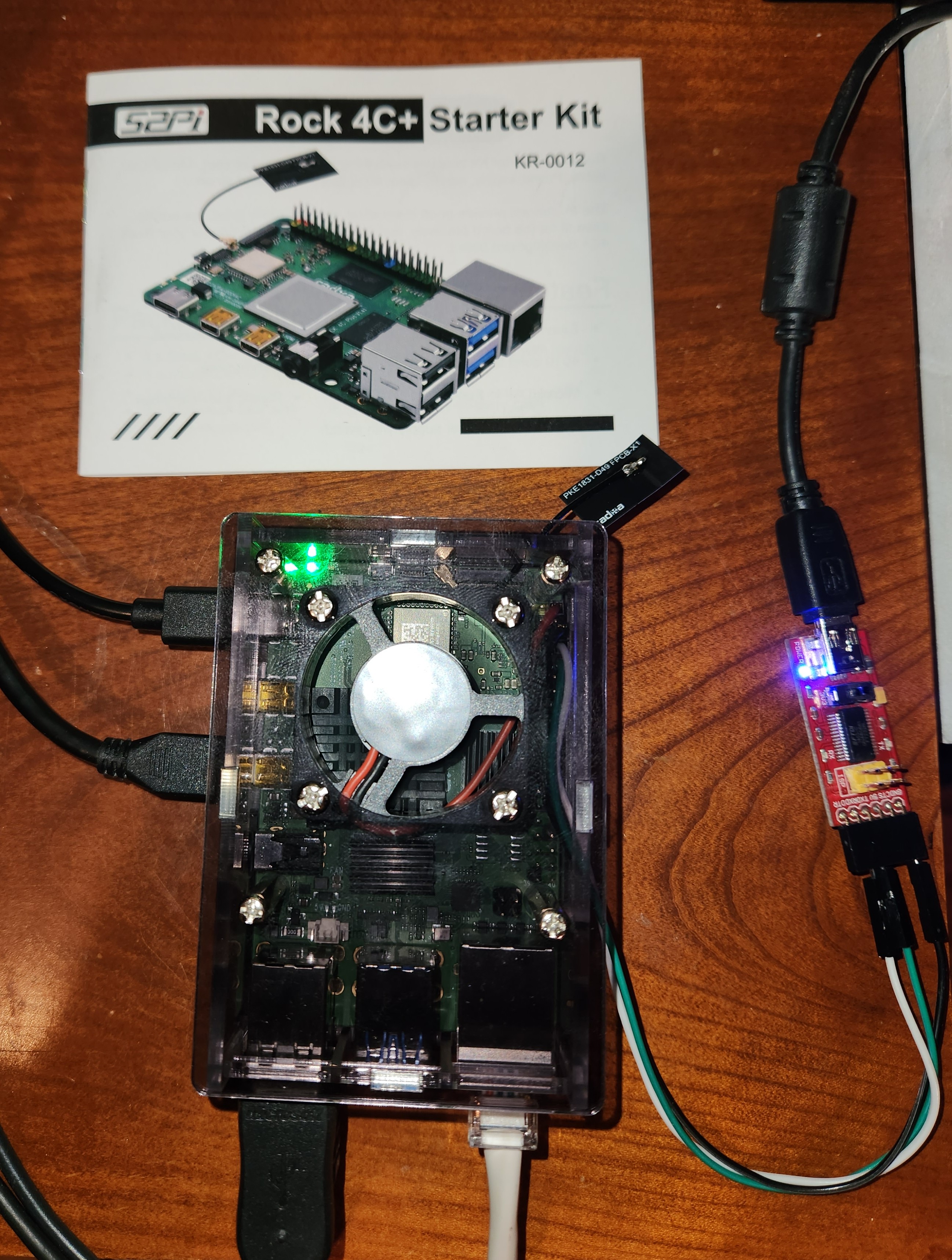
| 02:24, 28 September 2023 | 20230927 212510.jpg (file) |  |
1.59 MB | Rock 4c+ in operation. Again shown here with UART connected via FTDI/USB to PC for u-boot serial console. Photo by user | 1 |
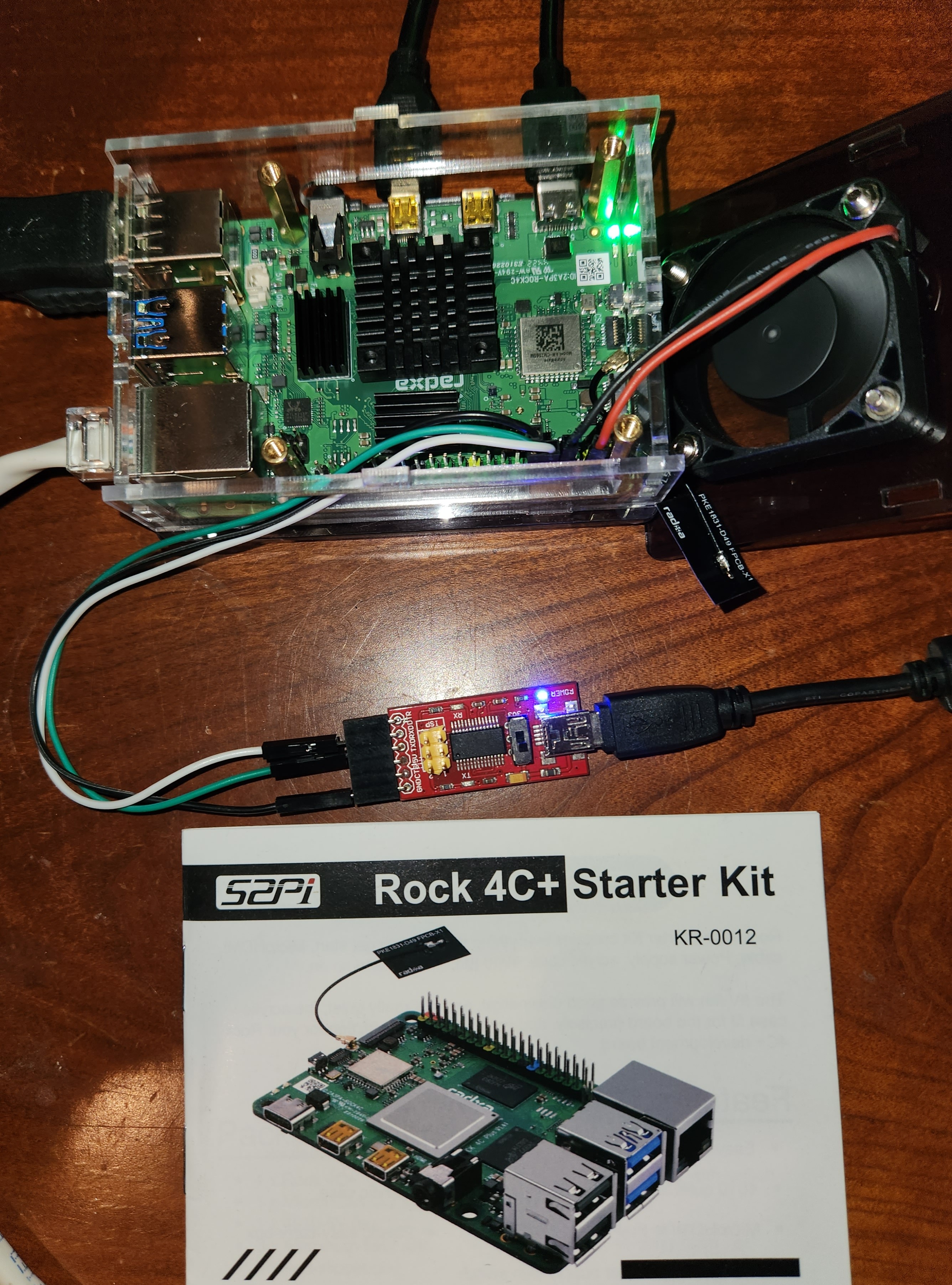
| 02:24, 28 September 2023 | 20230927 212105.jpg (file) |  |
1.35 MB | Rock 4c+ in operation. Again shown here with UART connected via FTDI/USB to PC for u-boot serial console. Photo by user | 1 |
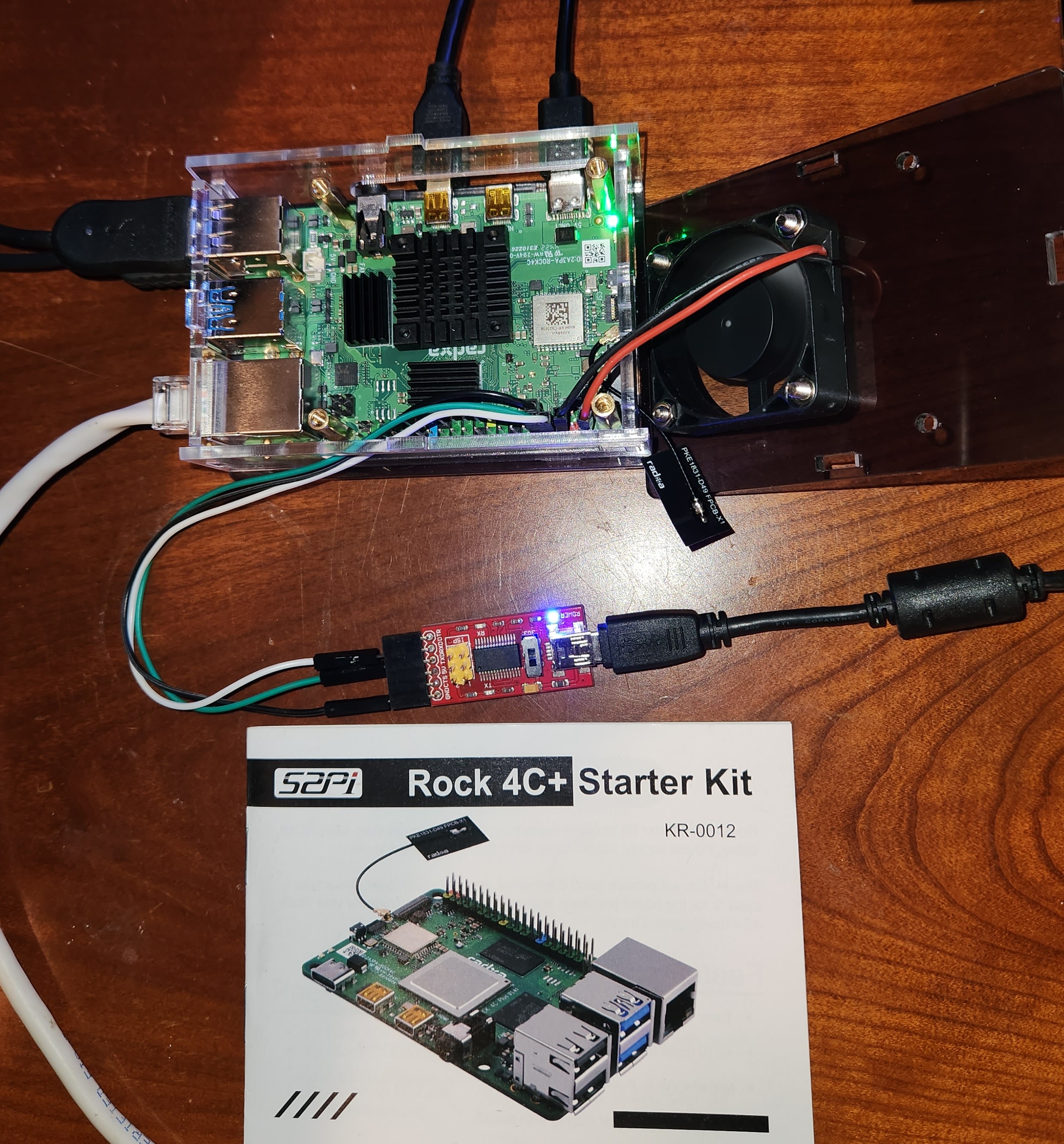
| 02:22, 28 September 2023 | 20230927 212050.jpg (file) |  |
1.83 MB | Rock 4c+ in operation. Shown here with UART connected via FTDI-USB to a PC for u-boot serial console. | 1 |