Gentoo on Hawk
Building on Gentoo on Mudan, which is an Applied Micro X-Gene 1 CPU, we have Gentoo on Hawk.
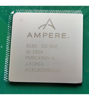
The Hawk motherboard is a 32 core Ampere Computing eMAG 8180 CPU. There is some history to be aware of here. The Applied Micro ARM IP was sold to Ampere Computing after Applied Micro had been manufacturing and distributing the X-Gene 1 and X-Gene 2 ARM64 CPUs. Simplistically, think of the X-Gene 3 as four X-Gene 1 CPUs in the same package.
The X-Gene 3 was sampled, then the story passes to Ampere Computing.
The Ampere eMAG 8180 is based on the X-Gene 3
The board is intended to be used in an openEDGE half width 1U chassis, which makes finding a commodity case a challenge. However, it does expect standard ATX power, so powering it up and operating it is not a problem.
Get going
All the electronics in the Hawk are static sensitive. Antistatic precautions are required
Cooling
Do not operate the system with only natural convection cooling for the CPU
The Hawk is intended to be fitted to a 1U half width chassis and use six fans for cooling.
With a 2200 RPM, 8cm fan mounted directly on the heatsink, the CPU reached 95°C at 90W CPU input power. Its rated at 125W too.
Even at 13W idling at the prompt, the CPU runs at 47°C
Boot/rescue media
Use the rescue mode of debian-10.4.0-arm64-xfce-CD-1.iso to boot, write efivars and so on. It will only drive the serial over LAN console.
dd it to a USB stick. The Hawk firmware says it can boot from CDROM but that's not confirmed.
DDR4 RAM
Do use Registered ECC DIMMs. I did test unregistered non ECC RAM from my main AMD64 system and it would not boot.
All the reference material says to fit in pairs but my Hawk is running quite happily on one. In the CH0_DIMM0 slot. This may be related to the memory in use, others have found that the board won't boot with just a single DIMM seated. The eMAG 8180 CPU can support two DIMMS per channel but only DIMM0 sockets are fitted on the Hawk.
The reference material uses different identifies for the RAM. The above is the silk screening on the board.
The connector numbers are silk screened onto the board in tiny text
Storage
Take your pick from SATA3 or NVME 4 lane PCIe. Being lazy, I put the Mudan SATA boot drive in to see what would happen. While the USB hardware and drivers are USB3, only USB2 ports are fitted. That's OK to get you going but not for long term use.
Kernel changes
Notice the absence of SATA on the PCIe bus:
root #lspci -nnk0000:00:00.0 PCI bridge [0604]: Ampere Computing, LLC eMAG PCI Express Root Port 0 [1def:e005] (rev 04) Kernel driver in use: pcieport 0002:00:00.0 PCI bridge [0604]: Ampere Computing, LLC eMAG PCI Express Root Port 2 [1def:e007] (rev 04) Kernel driver in use: pcieport 0002:01:00.0 USB controller [0c03]: Renesas Technology Corp. uPD720201 USB 3.0 Host Controller [1912:0014] (rev 03) Kernel driver in use: xhci_hcd 0004:00:00.0 PCI bridge [0604]: Ampere Computing, LLC eMAG PCI Express Root Port 4 [1def:e009] (rev 04) Kernel driver in use: pcieport 0004:01:00.0 Non-Volatile memory controller [0108]: Sandisk Corp Device [15b7:5030] (rev 01) Subsystem: Sandisk Corp Device [15b7:5030] Kernel driver in use: nvme 0006:00:00.0 PCI bridge [0604]: Ampere Computing, LLC eMAG PCI Express Root Port 6 [1def:e00b] (rev 04) Kernel driver in use: pcieport 0006:01:00.0 Ethernet controller [0200]: Intel Corporation I210 Gigabit Network Connection [8086:1533] (rev 03) Subsystem: Intel Corporation Ethernet Server Adapter I210-T1 [8086:0002] Kernel driver in use: igb 0007:00:00.0 PCI bridge [0604]: Ampere Computing, LLC eMAG PCI Express Root Port 7 [1def:e00c] (rev 04) Kernel driver in use: pcieport 0007:01:00.0 PCI bridge [0604]: ASPEED Technology, Inc. AST1150 PCI-to-PCI Bridge [1a03:1150] (rev 04) Subsystem: ASPEED Technology, Inc. AST1150 PCI-to-PCI Bridge [1a03:1150] 0007:02:00.0 VGA compatible controller [0300]: ASPEED Technology, Inc. ASPEED Graphics Family [1a03:2000] (rev 41) Subsystem: ASPEED Technology, Inc. ASPEED Graphics Family [1a03:2000] Kernel driver in use: ast
The kernel needed three changes from the X-Gene 1 kernel:
- Max CPUs 32, not 8.
- The Intel IGB network driver added
- SATA_AHCI_PLATFORM added to be able to see the AHCI ports.
The device
0002:01:00.0 USB controller [0c03]: Renesas Technology Corp. uPD720201 USB 3.0 Host Controller [1912:0014] (rev 03)
is fitted to the PCIe slot.
Kernel Parameters
A 5.15.x kernel is required as a get-u-going measure
Kernels later than 5.15.x require rcutree.use_softirq=0 on the kernel command like. This appears to avoid RCU timeout errors.
Its not well tested yet as my system only has about 28 days of uptime on the host and two KVMs combined. That's not a record, but it beats lots of other attempts.
efibootmgr
efibootmgr --create with gentoo-sources-6.1.1 gives RCU timeout errors, even with rcutree.use_softirq=0 on the kernel command line. The command never completes and only the SoL console works. I only tested twice, then reverted to gentoo-sources-5.15.x (without rcutree.use_softirq=0) so that's the workaround.
IPMI control
The Board Management Computer (BMC) is a ST2500. Use impitool on a remote host and enjoy all the good things that IPMI offers.
Activate the ADMIN login with password ADMIN, if required. e.g. after a factory reset.
user $ipmitool -I lanplus -H $REMOTEHOST -U ADMIN -P ADMIN raw 0x32 0x91 1Then get three ipmi shells with
user $ipmitool -I lanplus -H $REMOTEHOST -U ADMIN -P ADMIN shellin three console windows.
One for power control, one for the debug Serial over LAN (SoL) console, and one for the SoL console. Using each ipmi shell,
ipmitoolsol activateipmitoolsol activate instance=2and
ipmitoolchassis power <power_command>There are two more consoles too:
- The VGA console;
- the KVM console in the web interface.
The SoL console, VGA console and the KVM console all show different things.
Debug Sol example
Expect to see:
root #ipmitool -I lanplus -H 192.168.100.236 -U ADMIN -P ADMIN shellipmitool> sol activate instance=2 [SOL Session operational. Use ~? for help] DRAM FW v191001 DRAM Region[0]: 0x0080000000 - 0x00FFFFFFFF DRAM Region[1]: 0x0880000000 - 0x0FFFFFFFFF DRAM Region[2]: 0x8800000000 - 0x8FFFFFFFFF MCU[0]-Slot[0]: RDIMM[ID:ce80] M393A4K40BB2-CTD 32GB 2 rank(s) x4 > 2667 MCU[4]-Slot[0]: RDIMM[ID:ce80] M393A4K40BB2-CTD 32GB 2 rank(s) x4 > 2667 DRAM: 64GB DDR4 2667 ECC NOTICE: Booting Trusted Firmware NOTICE: BL1: v1.2(release):1.02.200626 NOTICE: BL1: Built : 03:15:07, Jun 27 2020 NOTICE: BL1: Booting BL2 NOTICE: BL2: v1.2(release):1.02.200626 NOTICE: BL2: Built : 03:15:07, Jun 27 2020 NOTICE: BL1: Booting BL31 NOTICE: BL31: v1.2(release):1.02.200626 NOTICE: BL31: Built : 03:15:07, Jun 27 2020
on the debug SoL console at power up.
If it continues,
root #...Error: MCU4 {---U}
Error Info: ecc_errcl 0x0
Error Info: ecc_errch 0x0
Error Info: ecc_errdl 0x1
Error Info: ecc_errdh 0x0
Error Info: ram_err 0x0then the RAM in MCU 4 is probably faulty.
or
root #...[SOL Session operational. Use ~? for help] DRAM FW v191001 PHY calibrating ... ERR: MCU[4]: *** Write Leveling DMC status doesn't go idle: -1 *** ERR: MCU[4] - PHY Training Failure ERR: PHY training error [-1]
Is the RAM in MCU[4] plugged in properly ?
Web interface
There is a web interface at https://$REMOTEHOST. openwebstart is not required. Default login is ADMIN/ADMIN, it allows to flash the firmware, see sensor readings, and most interestingly to access the console/KVM via an HTML5 viewer. Its (web-based) support to boot from iso files works very well, and as such you don't have to use a debian boot cd or anything, but just take the latest Gentoo arm64 livecd to boot and install the machine.
Power requirements
With the hardware configured as below:
- A 700W PSU
- The Hawk Board
- One 32G RDIMM-2666
- Two SATA3 SSDs in Raid 1
- One 2200 RPM 8cm fan
- Off, with 5vSTBY applied <5W
- One user logged in over ssh, otherwise idle 39W
- Building glibc with MAKEOPTS="-j32" 137W (Max)
- Building the kernel with make -j40 148W max (CPU Temp 93°C with a 22°C ambient.
All power readings measured at the input to the PSU.
For completeness. The power factor is about 0.6. That's pretty terrible but its not user adjustable.
Random nuances
Serial port
The serial port is ttyS0 until openrc starts, then it becomes ttyAMA0. The kernel command line needs
console=tty0 console=ttyS0,115200n8 console=ttyAMA0,115200n8
to see everything except a login prompt on serial console.
The login prompt requires ttyAMA0 in /etc/inittab
# SERIAL CONSOLES
s0:12345:respawn:/sbin/agetty -L 115200 ttyAMA0 vt100
PCIe slot
The references say that it is PCIe Gen 3, backwards compatible with Gen 1 and Gen 2. I can report that out of three cards I tested two caused boot failures in the firmware.
The two cards that caused boot failures in the firmware were network cards that support PXE booting. PXE provides on card code to execute on the host CPU. Oops, that will be AMD64 code then. The idea is that its enough to boot the host over the network. That used to be an optional extra on PCI network cards.
Read the fine print before you invest in a network card for the Hawk.
With a four lane dual USB 3.0 and dual SATA3 card, (no ROMs) it boots and lspci for the stot says
user $lspci0002:00:00.0 PCI bridge: Ampere Computing, LLC eMAG PCI Express Root Port 2 (rev 04) 0002:01:00.0 PCI bridge: PLX Technology, Inc. PEX 8608 8-lane, 8-Port PCI Express Gen 2 (5.0 GT/s) Switch (rev ba) 0002:02:01.0 PCI bridge: PLX Technology, Inc. PEX 8608 8-lane, 8-Port PCI Express Gen 2 (5.0 GT/s) Switch (rev ba) 0002:02:05.0 PCI bridge: PLX Technology, Inc. PEX 8608 8-lane, 8-Port PCI Express Gen 2 (5.0 GT/s) Switch (rev ba) 0002:02:07.0 PCI bridge: PLX Technology, Inc. PEX 8608 8-lane, 8-Port PCI Express Gen 2 (5.0 GT/s) Switch (rev ba) 0002:02:09.0 PCI bridge: PLX Technology, Inc. PEX 8608 8-lane, 8-Port PCI Express Gen 2 (5.0 GT/s) Switch (rev ba) 0002:03:00.0 USB controller: NEC Corporation uPD720200 USB 3.0 Host Controller (rev 03) 0002:04:00.0 SATA controller: Marvell Technology Group Ltd. 88SE9120 SATA 6Gb/s Controller (rev 12)
Which looks good for the card in the PCIe slot.
TODO: The BIOS supports PCIe bifurcation, so the one 16 lane PCIe slot can be operated as two 8 lane slots. Take care sourcing a bifurcation card. Ensure that the two 8 lane slots will be over the Hawk motherboard.
Migrating QEMU/KVMs
The Hawk does not support GIC_v2. Use
root #virsh edit <domain> <features>
<acpi/>
<gic version='2'/>
</features>
to change to gic version='3'
Thermal Sensors
The thermal sensors appear to have a range from 0..255°C. At least, the CPU Diode Temp is reported as 2.5500000000e+02 in an ambient air temperature of about -5°C. The system still works too.
Mechanical considerations
Arranging the parts
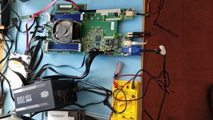
Without a case, the Hawk parts were spread out on the anti-static mat on my electronics workbench as illustrated.
Points to note:
- The board is mounted on 3mm stand offs to keep it away from the conductive surface.
- The ATX PSU is below the board. It won't need 700W, I hope.
- The HDD is at the left.
- The faulty RAM stick is at the top.
Cooling
CPU Cooling (Limited)
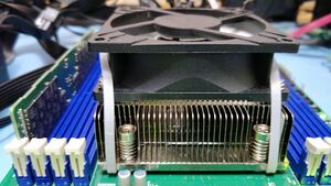
An 8cm fan can be retained to the heatsink with a couple of cable ties as illustrated.
This is not adequate cooling. With 24 cores running, the CPU is 70°C above the ambient temperature. You need to replace the passive cooling fan with an active or water-cooled solution.
The fan is spaced off the heatsink with normal fan fixing screws. This was required to prevent the rotor clipping the heatsink fins.
There are a few disadvantages to this.
- The solid rotor centre is very close to the fins which will be bad for cooling that part of the heatsink.
- A soft mounting will probably be lower noise.
Whatever, the CPU needs to be kept under 96°C, which is the Upper Non-Critical temperature.
ipmitool> sensor get CPU_Temp
Locating sensor record...
Sensor ID              : CPU_Temp (0x1)
 Entity ID             : 30.1
 Sensor Type (Threshold)  : Temperature
 Sensor Reading        : 57 (+/- 16) degrees C
 Status                : ok
 Lower Non-Recoverable : 5.000
 Lower Critical        : 9.000
 Lower Non-Critical    : 20.000
 Upper Non-Critical    : 90.000
 Upper Critical        : 96.000
 Upper Non-Recoverable : 100.000
 Positive Hysteresis   : Unspecified
 Negative Hysteresis   : Unspecified
CPU Cooling
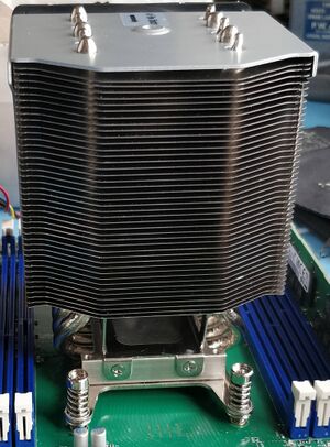
There are images of a similar motherboard fitted with A Supermicro SNK-P0050AP4 cooler. Start reading at eMag Workstation by Avantek and zoom into the images in the linked hardware review. The part number on the side of the CPU cooler is clearly visible in one of the images.
Having fitted the Supermicro SNK-P0050AP4 cooler to my Hawk, I can say that no metalwork is required but the bottom fan fixings will foul the last two DIMM slots. It is possible to modify the fan fixings.
The CPU runs less than 40°C above ambient with all 32 cores building a kernel.
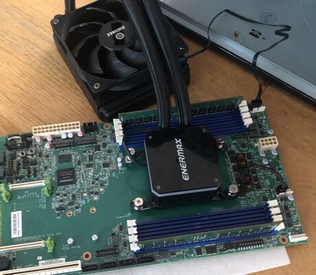
Alternative is to buy a water-cooled unit (these usually go with LED lights in them, as they are intended for case-mod-ers), make sure you have support for the narrow mounting pattern, or be prepared to bend some of the AMD frames to fit. Doing so is a business which requires some luck, but surely no fun.
The exact specs of the CPU socket are: an LGA 2011 narrow ILM (56×94 mm mounting pattern), also known as Intel's Socket R. The CPU itself is a 50x50mm square.
Removing the 1U heatsink
Slacken the fixing/jacking screws half a turn at a time, first half a turn on one diagonally opposite pair, then half a turn on the other diagonally opposite pair. This is the risky operation. One of two things will happen. The heatsink will come away from the CPU or the CPU will be pulled off its solder balls. If the latter happens, its a very expensive process to fix.
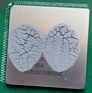
My Hawk was fitted with far too much thermal paste and the heatsink lifted off the CPU. Thermal pads tend to set hard and bond the heatsink to the CPU, which for socketed CPUs removes the CPU from the socket. The eMAG 8180 is not socketed. Anyway, it did not use a thermal pad, so all was well.
Cleaning the old thermal paste
Use cotton wool balls soaked in Methylated Spirits (Wood alcohol) to remove the thermal paste. It cannot be reused as it tends to dry out. It gets everywhere. Clean up as you go and do not keep the used cotton wool balls indoors. Methylated Spirits is highly inflammable.
Putting it together
Assemble the narrow mount to the SNK-P0050AP4 cooler. Remove the fan housing by sliding it vertically off the heatsink. It has a retaining screw on the top. A trial fit should not be required but measure twice cut once.
A few words about thermal paste.
Thermal paste is actually a fairly good thermal insulator but its a much better thermal conductor than air. When two flat plates touch, they touch at exactly three points, like a tripod. In our case, the plates are the the heat spreader on the top of the CPU and the CPU cooler contact surface. Other than the three points, there is a thin layer of air between the mating surfaces.
The idea of adding thermal paste is to displace the air. No more. Its very easy to use too much thermal paste. Its also easy to fix.
Put the thermal paste in and assemble the heatsink to the CPU, then remove it. If the paste covers the CPU and squeezes out of the sides, that's far too much. Clean off one surface only (about 50% of the paste) and test again.
This image confirms the dial gauge measurements made with all the pieces separately. That the cooler fits properly.
The heatsink fixing, which defines the plane of the heatsink and CPU coplanarity is in error by 0.6mm on my sample. That's a huge error to take up with thermal paste. I slowly added more thermal paste.
Voltage regulator cooling
The voltage regulators, there are lots, are located in the area around the 12v_ATX connector.
Convection cooling is not adequate for voltage regulator cooling. The first one that complained was the PMD_VRD_Temp, which went critical even under light loads. Forced air cooling of this area is essential if the server is going to be operating at any more than a tickover.
The voltage regulators have a large pad on the bottom, almost the entire area of the chip. This serves as both the output pin and to conduct heat into the motherboard. Think 20A at 1v output. Air flow over both sides of the motherboard is probably a good idea.
Fan Control
Manual fan control using ipmitool works
From the ipmitool shell
ipmitoolraw 0x3c 0x3 0x01just once, followed by
ipmitoolraw 0x3c 0x4 A BA is the fan number in the range 1..6 for the Hawk.
B is the desired fan speed in the range 0..100. Fan speed is a decimal number.
Fan settings are not saved across BMC power cycles. They default to 100% which is noisy but safe.
User changes to sensor thresholds are lost across BMC power cycles too. This results in lots of spurious alarms when the Hawk is used with non-standard cooling.
Heating
The authors Hawk is installed in an unheated outhouse (garage). It gets too hot for the hawk in the summer and too cold in the winter. The system has crashed with a "Fatal Exception in Interrupt" Kernel Panic that coincides with an overnight frost, three times this year. Further, it has produced the same error message on several attempts to reboot too. Possibly until it self heats a little?
That does not establish cause and effect. However, the Non-Recoverable lower thermal limits have been breached, so its operating outside of its lower thermal limits during the cold weather.
The PCI Express slot
It is not possible to fit a standard PCIe card into the PCIe slot as the bottom end of the bracket will hit the power switch. A right angle riser card is expected to be used. Either modify the bracket or relocate the power switch.
I did look on the web for a right angle PCIe riser card. There are lots but they are all the wrong handedness. However, I found a PCIe extender card in my box of bits which is just enough to lift a normal card bracket above the switch. However, with vertical mounting, the back of the PCIe card fouls straight SATA connectors.
Finding a case
Standard ATX cases
The Hawk back panel is too wide for a commodity PC case back plate opening. Maybe it can be made to fit with some metalwork?
eMag Workstation by Avantek is the eMag Raptor system in a modified case. The Hawk and Raptor are different form factors but there may be some hints there.
By default a board would be attached to the side of the case, to allow for wider mainboards. The Hawk board, however is in comparison quite narrow. In fact, its width fits quite nicely at the bottom of the case, and the length is a few centimetres smaller. Unfortunately, most cases have some construction inside the case that reserve space for disks or sliders for longer PCI cards. This needs removal, for which the construction of the case gets compromised, so make sure the case still remains solid enough to house the board safely.
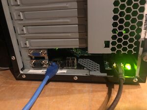
By removing the lower two card slots, enough space is created for the connector side of the Hawk board, allowing the network connectors, USB and VGA/serial connectors to be reachable. Note that this requires removing part of the case that is not used for the removable slots.
Since the Hawk board would normally be in a chassis (case) that forces a well-controlled airflow using 6 fans from the CPU side to the connector side, it is important to keep a good airflow to provide cooling for the entire board. In this ATX case there's two 12cm fans that generate an airflow from front to the back of the case, since the ATX PSU is directing its airflow in the same way. Since this airflow is nowhere near as directed and strong as in a flat chassis, the CPU passive fan needs replacing with something better. In this case, a water-cooled solution was chosen with a single fan that is on the case, also providing the main airflow. Without doing this the machine frequently overheats (e.g. using a 9cm fan on top of the passive fan, you may have some success but run into problems when putting the CPU under stress, if you must, try positioning the fan from the centre, such that the centre gets cooled -- this is where the CPU actually is -- maybe use two 9cm fans next to each other.)
The Hawk board itself is attached to the bottom of the ATX case by using regular screws and "golden" pins that usually are screwed in the side-plate at the correct positions, Here, to lift the board to the right level, so its connectors are available, hot-glue was used to attach the pins to the bottom, as such the board is "floating" free, while still being fixed to the bottom of the case.
3D Printed Case
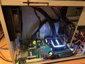
There is a Printed Case if you have access to a 3D printer. It also deals with the cooling problem.
Sun U10 case
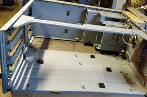
A Sun U10 case, with the electronics removed is about right.
The PCI card cage is still fitted
Remove the PCI card cage carefully by drilling out the rivets that hold it to the rear of the chassis and bending up the two tabs. Keep it for later. Its just the right size to become a PCIe card cage, once it has been trimmed to clear the Hawk. Put it to one side.
Keep all the metalwork until you are sure it will not have a place in your hawk.
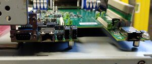
Remove the old motherboard stand offs then make two small hacksaw cuts toallow clearance for the VGA connector. I cut the clearance for the VGA connector, then fitted shorter spacers to accommodate full height PCIe cards with the bracket still fitted.
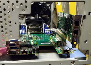
Careful placement allows unmodifed half height PCIe cards to be fitted but there is no support for the backplate.
The PCIe extender can be seen in the PCIe slot in the above image.
Full height cards would need the motherboard mounted on smaller stand offs than the 15mm x M3 I had to hand. That's probably worth while. My system uses spacers, for a screw each side, as its easier to slot a hole for a screw than to move a tapped hole that's in the wrong place.
The image above shows a large clearance above the VGA connector and a half height PCIe card fitted.
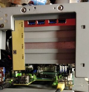
The PCI card cage, removed above, can be refitted (after trimming) and will serve as a PCIe card cage.
The motherboard PCIe slot is connected to the 4 port USB3 card using a 30cm PCIe 16 lane extender cable.
Two small hacksaw cuts, or a touch with the angle grinder, are required to clear the power input connector on an ATX PSU.
The original front fan has been replace by a 140mm fan. That's almost the width of the Hawk board, so there should be plenty of cooling for the on board power regulators. One of them gives critical lower critical temperature going low warnings now.
See also
- Gentoo On X-Gene 1 Mudan — an AARCH64 (arm64) server board based on the APM X-Gene 1 CPU.

