File:Rpi3 wiring2.jpg
From Gentoo Wiki
Size of this preview: 637 × 599 pixels. Other resolutions: 255 × 240 pixels | 1,828 × 1,720 pixels.
Original file (1,828 × 1,720 pixels, file size: 401 KB, MIME type: image/jpeg)
Summary
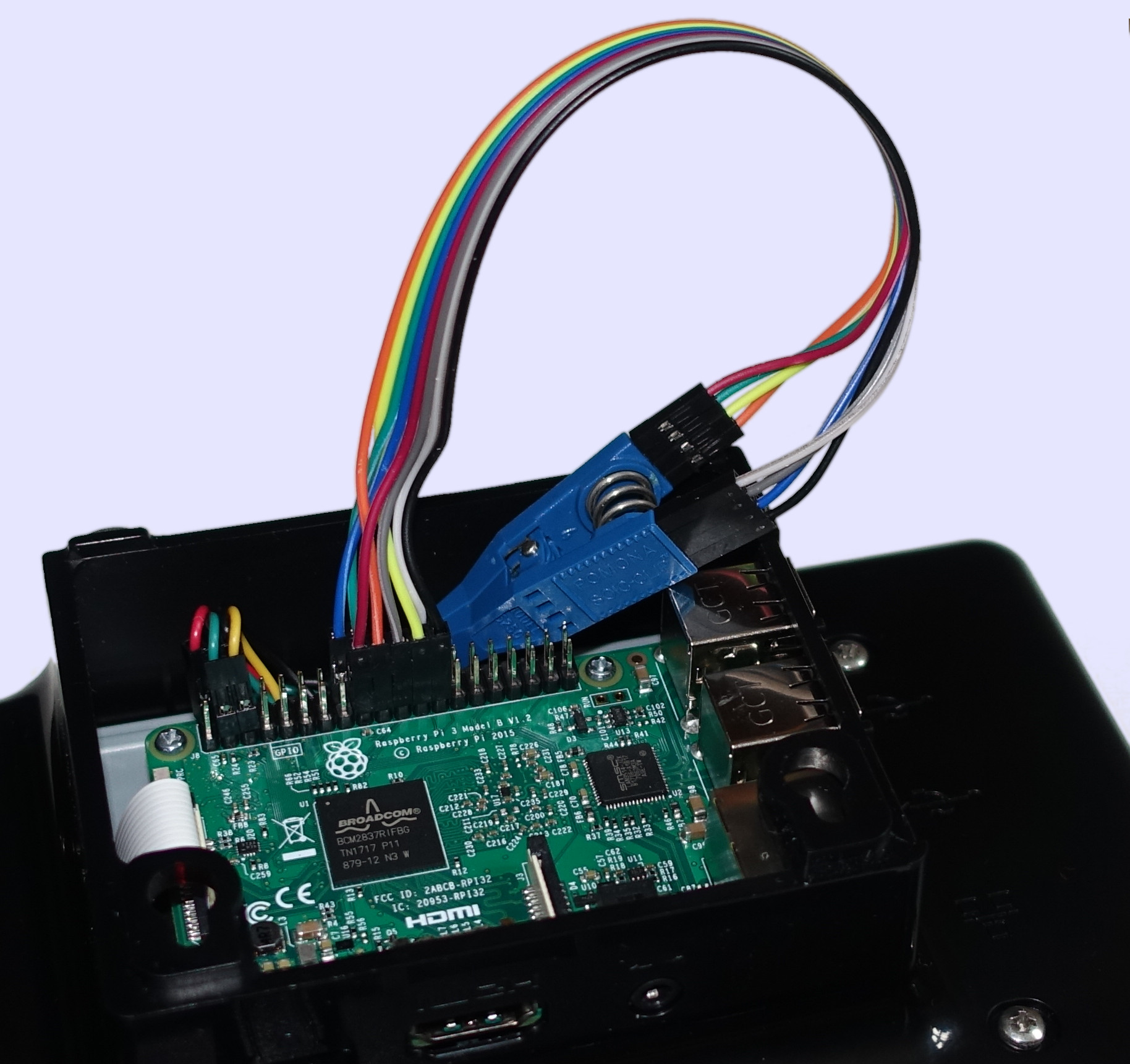
Photo showing wiring of an RPi3 SBC (in an official 7" touchscreen enclosure) to a Pomona 5250 SOIC clip, as used for in-circuit reprogramming of SOIC-8 flash chips. 20cm female-female Dupont semi-ribbon coloured jumper cables used. Uploaded initially for use in an addendum to Sakaki's EFI Install Guide.
Licensing
This asset is licensed under the terms of the Creative Commons Attribution-ShareAlike 4.0 International license.
You are free to share (copy, distribute and transmit the work) and remix (adapt the work), but you must attribute the author and distribute any derivative works you create under a similar license.
You are free to share (copy, distribute and transmit the work) and remix (adapt the work), but you must attribute the author and distribute any derivative works you create under a similar license.
File history
Click on a date/time to view the file as it appeared at that time.
| Date/Time | Thumbnail | Dimensions | User | Comment | |
|---|---|---|---|---|---|
| current | 11:48, 7 October 2017 | | 1,828 × 1,720 (401 KB) | Sakaki (talk | contribs) | Now showing pins 3 (/WP) and 7 (/HOLD) as connected to RPi3 GPIO pins 16 (GPIO_GEN4) and 18 (GPIO_GEN5); to allow them to be pulled high via RPi3's internal pull-up resistors. This is safer than leaving them floating. |
| 17:46, 4 October 2017 |  | 2,048 × 1,365 (368 KB) | Sakaki (talk | contribs) | Photo showing wiring of an RPi3 SBC (in an official 7" touchscreen enclosure) to a Pomona 5250 SOIC clip, as used for in-circuit reprogramming of SOIC-8 flash chips. 20cm female-female Dupont semi-ribbon coloured jumper cables used. Uploaded initially... |
You cannot overwrite this file.
File usage
The following page uses this file: