File:Rpi3 gpio header ic flash.png
From Gentoo Wiki

No higher resolution available.
Rpi3_gpio_header_ic_flash.png (570 × 450 pixels, file size: 70 KB, MIME type: image/png)
Summary
Shows pinout mapping from RPi3 GPIO header to a typical SOIC-8 flash chip (or 8 pin DIP, or Pomona-style IC-clip etc.). Uploaded initially for use in an addendum to Sakaki's EFI Install Guide
Licensing
This asset is licensed under the terms of the Creative Commons Attribution-ShareAlike 4.0 International license.
You are free to share (copy, distribute and transmit the work) and remix (adapt the work), but you must attribute the author and distribute any derivative works you create under a similar license.
You are free to share (copy, distribute and transmit the work) and remix (adapt the work), but you must attribute the author and distribute any derivative works you create under a similar license.
File history
Click on a date/time to view the file as it appeared at that time.
| Date/Time | Thumbnail | Dimensions | User | Comment | |
|---|---|---|---|---|---|
| current | 01:35, 8 October 2017 | | 570 × 450 (70 KB) | Sakaki (talk | contribs) | Fix incorrect pin name (CS -> /CS) |
| 01:27, 8 October 2017 | 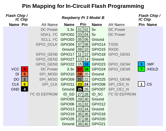 | 570 × 450 (70 KB) | Sakaki (talk | contribs) | Add missing names for pins 3 and 7. | |
| 12:25, 7 October 2017 |  | 570 × 450 (69 KB) | Sakaki (talk | contribs) | Fix missing pin mapping colours on GPIO header pins 16 and 18. | |
| 11:45, 7 October 2017 | 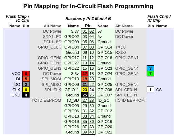 | 570 × 450 (69 KB) | Sakaki (talk | contribs) | Now showing pins 3 (/WP) and 7 (/HOLD) on IC connected (to GPIO_GEN4 and GPIO_GEN5, pins 16 and 18, on RPi3 GPIO header, respectively). This way they can be pulled to 3.3v via the RPi3's internal pull-up resistors (using the gpio utility), which is sa... | |
| 12:10, 4 October 2017 | 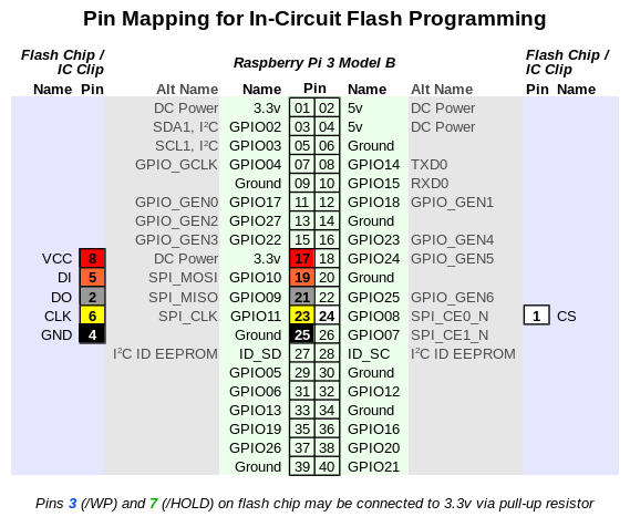 | 569 × 476 (74 KB) | Sakaki (talk | contribs) | Shows pinout mapping from RPi3 GPIO header to a typical SOIC-8 flash chip (or 8 pin DIP, or Pomona-style IC-clip etc.). Uploaded initially for use in an addendum to Sakaki's EFI Install Guide |
You cannot overwrite this file.
File usage
There are no pages that use this file.